
REGDOC-2.5.6, Design of Rooms Where Unsealed Nuclear Substances Are Used
Preface
This regulatory document is part of the CNSC’s physical design series of regulatory documents, which also covers activities that impact the ability of structures, systems and components to meet and maintain their design basis given new information arising over time and taking changes in the external environment into account. The full list of regulatory document series is included at the end of this document and can also be found on the CNSC’s website.
Regulatory document REGDOC-2.5.6, Design of Rooms Where Unsealed Nuclear Substances Are Used, clarifies requirements and provides guidance and a recommended approach for meeting the room design requirements in paragraph 3(1)(l) of the Nuclear Substances and Radiation Devices Regulations. It also clarifies requirements and provides guidance on performing radiation dose estimates to keep doses as low as reasonably achievable (ALARA), pursuant to paragraph 4(a) of the Radiation Protection Regulations.
This document is the first version and supersedes GD-52, Design Guide for Nuclear Substance Laboratories and Nuclear Medicine Rooms (May 2010).
The information in this document is consistent with modern national and international practices for addressing issues and elements that control and enhance nuclear safety. In particular, this document establishes a modern, risk-informed approach to the design of rooms where unsealed nuclear substances are used.
For information on the implementation of regulatory documents and on the graded approach, see REGDOC-3.5.3, Regulatory Fundamentals.
The words “shall” and “must” are used to express requirements to be satisfied by the licensee or licence applicant. “Should” is used to express guidance or that which is advised. “May” is used to express an option or that which is advised or permissible within the limits of this regulatory document. “Can” is used to express possibility or capability.
Nothing contained in this document is to be construed as relieving any licensee from any other pertinent requirements. It is the licensee’s responsibility to identify and comply with all applicable regulations and licence conditions.
Table of Contents
- 1. Introduction
- 2. Licensing process for using unsealed nuclear substances
- 3. Design Requirements and Guidance for Sections B to H of the Design Assessment Form
- 3.1 Finishing and fixtures – section B of the design assessment form
- 3.2 Emergency facilities and general contamination control considerations – section C of the design assessment form
- 3.3 Plumbing – section D of the design assessment form
- 3.4 Access control – section E of the Design Assessment Form
- 3.5 External dose control – section F of the design assessment form
- 3.6 Waste – section G of the design assessment form
- 3.7 Room ventilation and air flow – section H of the design assessment form
- 3.8 Ducts, vents and stacks – section I of the design assessment form
- 3.9 Fume hood design – section J of the design assessment form
- 3.10 Hot cell design – section K of the design assessment form
- 4. Dose estimates for rooms classified as high-level, containment-level, nuclear medicine – other and nuclear medicine – radiopharmacy
- Appendix A: Estimating Doses
- Appendix B: Summary of Requirements and Guidance for Design Assessment Forms
- Glossary
- References
- Additional Information
1.Introduction
1.1 Purpose
REGDOC-2.5.6, Design of Rooms Where Unsealed Nuclear Substances Are Used, clarifies requirements and provides guidance for licensees who work with unsealed nuclear substances.
1.2 Scope
The document includes information on finishings and fixtures, emergency facilities and general contamination control considerations, plumbing, access control, external dose control, waste, room ventilation and air flow, ducts, vents and stacks, fume hood design, hot cell design and dose estimation for the various room classifications (intermediate-level, high-level, containment-level or nuclear medicine).
This document is intended for the following classes of licences:
- Class II Nuclear Facility and Prescribed Equipment
- Nuclear Substance and Radiation Devices
However, the information provided may also be useful for other classes of licences.
1.3 Relevant legislation
The following provisions of the Nuclear Safety and Control Act (NSCA) and the regulations made under it are relevant to this document:
- NSCA, subsection 24(4)
- General Nuclear Safety and Control Regulations (GNSCR), section 3 and paragraph 12(1)(c)
- Nuclear Substances and Radiation Devices Regulations (NSRDR), paragraph 3(1)(l)
- Radiation Protection Regulations (RPR), subparagraph 4(a)(iii)
2. Licensing process for using unsealed nuclear substances
As part of the process to obtain a licence for the use of unsealed nuclear substances, applicants must submit a completed licence application in accordance with section 3 of the GNSCR, section 3 of the NSRDR and section 4 of the RPR. More information about the design of rooms being proposed in a licence application can be found in:
- REGDOC-1.4.1, Licence Application Guide: Class II Nuclear Facilities and Prescribed Equipment Footnote 1
- REGDOC-1.6.1, Licence Application Guide: Nuclear Substances and Radiation Devices, version 2 Footnote 2
If required, a dose estimation must also be submitted. Refer to section 4 of this document for information related to dose estimates.
For ease of application, the CNSC recommends that applicants complete the relevant Design Assessment Form (DAF) in Appendix B when applying for any new construction, major renovation and/or change to the licensed activities in a room where unsealed nuclear substances will be used. DAFs are a tool to assist applicants in gathering the information required, but they are not themselves required. Applicants can submit the required information in other forms, provided it meets the criteria laid out in this document. For the purposes of this document, required design information shall hereafter be referred to as “DAF.”
In addition, Appendix B provides a summary of requirements and guidance applicable for each room classification, which can also be used as a checklist when completing the DAF. For example, a DAF should be completed when:
- demolishing walls
- changing existing shielding
- changing the total annual and/or per use activities of nuclear substances
- adding nuclear substances
- installing a new fume hood or making changes to the ventilation systems
- undergoing renovations that change the shielding of the room or the source-receptor distance
- using mobile units (i.e. a temporary and/or movable room where unsealed nuclear substances are used)
The completed DAF should be submitted to the CNSC as early as possible in the design stage in order to facilitate the assessment of the licence application or amendment. If multiple rooms of similar design and function are to be constructed or renovated, only one DAF needs to be submitted.
Where more than one room for using unsealed nuclear substances is to be constructed or renovated, and the designation or use of each one is different, a separate DAF should be submitted for each room. CNSC staff may request additional information after the initial design or renovation assessment is completed.
Any modification to a room where unsealed nuclear substances are used may require review if changes are made to the initial design. If unsure whether a revised DAF should be submitted, licensees should consult their CNSC licensing contact.
2.1 Classification of rooms
Table 1 outlines the classifications of rooms where unsealed nuclear substances are used and their respective criteria/descriptions. With the exception of basic-level rooms, all other room classifications require the written approval of the Commission or a person authorized by the Commission for the use of unsealed nuclear substances.
All areas, rooms or enclosures where more than one exemption quantity of an unsealed nuclear substance is used must be classified as basic, intermediate, high or containment-level rooms, according to the maximum activity of any nuclear substances to be used in the room at one time (see table 1), including all rooms where veterinary nuclear medicine activity is performed.
Table 2 outlines the nuclear medicine classification in the areas, rooms or enclosures where nuclear substances are prepared for or administered to a person. This classification is specific to nuclear medicine licence use types issued (for the purposes of diagnostic, therapeutic and human research studies). The radiopharmacy located in a nuclear medicine department shall be classified as a nuclear medicine room; however, for design purposes, applicants must follow the requirements and guidance described for the intermediate, high or containment-level room classification, depending on the quantity of unsealed nuclear substances used at a single time. For the purpose of this document, nuclear medicine rooms are separated into one of two classifications: “nuclear medicine – radiopharmacy” and “nuclear medicine – other.”
| Classification of room | Criteria/description |
|---|---|
| Basic-level | The quantity of unsealed nuclear substance used at a single time does not exceed 5 times its corresponding annual limit on intake (≤ 5 ALI). |
| Intermediate-level | The quantity of unsealed nuclear substance used at a single time does not exceed 50 times its corresponding ALI (≤ 50 ALI). |
| High-level | The quantity of unsealed nuclear substance used at a single time does not exceed 500 times its corresponding ALI (≤ 500 ALI). |
| Containment-level | The quantity of unsealed nuclear substance used at a single time exceeds 500 times its corresponding ALI (> 500 ALI). |
| Nuclear medicine | Criteria/description |
|---|---|
| Areas, rooms or enclosures where nuclear substances are prepared for or administered to a person (via injection, inhalation or ingestion) for the purpose of diagnosis or treatment of patients, or for human research studies (excluding medical diagnostic X-rays or the medical use of sealed sources for brachytherapy or teletherapy treatments). | |
| Nuclear medicine – radiopharmacy | Follow the guidance and requirements described for the intermediate-level (≤ 50 ALI), high-level (≤ 500 ALI) or containment-level (> 500 ALI) room classification. |
| Nuclear medicine – other | Injection room, imaging room, therapeutic in-patient room or any other room routinely occupied by patients undergoing diagnostic or therapeutic procedures. |
Notes:
1. The appropriate ALI value is the one that best represents the risks associated with the nuclear substance. If it is not possible to determine whether the greater risk is related to the inhalation or ingestion of the substance, then the more restrictive value should be used. ALIs may be derived using the latest compendium of dose conversion factors (DCFs) published by the International Commission on Radiological Protection (ICRP) Footnote 3, by dividing 0.02 Sv by the DCF (Sv/Bq). For inhalation, the largest DCF for a 5 µm particle size should be used.
2. Tables 1 and 2 do not apply to rooms or enclosures used solely for storage of nuclear substances. In these circumstances applicants should follow the guidance given in section 3.5, “External Dose Control.”
3. In cases where more than one nuclide is used in a room, the room classification should be determined separately using each nuclide’s ALI and maximum handled activity. The most restrictive room classification result (i.e., highest) should be the level assigned to the room.
3. Design Requirements and Guidance for Sections B to H of the Design Assessment Form
This section outlines requirements and guidance for the design of rooms in which unsealed nuclear substances are used. The following requirements and guidance are risk-informed and corresponds to sections B to H of the DAF.
The DAF also provides opportunities to propose alternative means of achieving the intent of the requirements outlined in this section. Any alternative approach shall demonstrate that the ALARA principle is maintained.
Basic-level rooms do not require a design assessment and therefore do not require a DAF.
3.1 Finishing and fixtures – section B of the design assessment form
Requirements
The following applies to rooms classified as intermediate-level, high-level, containment-level, nuclear medicine – other, and nuclear medicine – radiopharmacy:
- B1 – Use flooring, work surfaces, chairs, cupboards and shelving that have a smooth, impervious and washable finish in areas where unsealed nuclear substances are used.
Guidance for all room classifications
Containing spills and other accidents is a prime concern in all rooms in which unsealed nuclear substances are used. As a result:
- B2 – Flooring should have a 1-piece design. If the flooring is more than 1 piece, all joints in the flooring material should be sealed. The joint between the flooring and the walls should be rounded to prevent spills from getting underneath them. Flooring should have a strippable coating to make decontamination easier, should an accident occur.
- B3 – All joints on work surfaces, including bench tops, should either be sealed or have a seamless 1-piece design.
- B4 – Countertops should include a lip or raised edge to prevent runoff onto the floor. If the countertop abuts a wall, the joint should also be rounded or the countertop should have a backsplash.
- B5 – Walls should be finished with a smooth and washable surface, and all joints should be sealed. This can make cleanup easier if a room is contaminated by back-spray from a vial or if some other similar event occurs.
- B6 – The ceiling should be finished with a smooth, washable surface, and all the joints should be sealed. Easily replaceable modular ceilings (e.g., drop ceiling with tiles) are also acceptable.
3.2 Emergency facilities and general contamination control considerations – section C of the design assessment form
Requirements
The following applies to all room classifications:
- C1 – Areas for food and drink preparation, consumption or storage are not located inside any room in which unsealed nuclear substances are used.
Note: The only exception to this requirement is where the patient’s consumption of food or drink is a necessary part of a nuclear medicine procedure. In such cases, only food and beverages intended for patients may be stored in the room, and only patients undergoing such studies may consume this food or beverages.
The following applies to rooms classified as high-level, containment-level and
nuclear medicine – radiopharmacy:
- C2 – Have personnel decontamination facilities appropriate to the activities and the nuclear substances and chemicals used.
- C3 – Have emergency lighting.
Guidance for all room classifications
- C4 – An accessible area should be designated to store materials and equipment used for decontamination and monitoring. Materials and equipment should include spill kits, survey meters and contamination meters appropriate for the nuclear substances and chemicals being used.
- C5 – Decontamination facilities should include a separate hand-washing sink near the entrance to the room.
- C6 – An emergency eye-wash station and an emergency shower should be located in or near the room.
- C7 – Personal contamination monitoring equipment suitable for the nuclear substances being used should be available at all points of entry/exit.
- C8 – Amenities like coat hooks, active laundry bins, storage lockers, etc., should be provided in the room near the entrance. This can facilitate the removal and proper storage of potentially contaminated personal protective equipment, such as lab coats, before leaving the room.
Guidance specific to nuclear medicine – other
- C9 – Nuclear medicine departments should have washrooms dedicated for use by patients undergoing nuclear medicine procedures.
- C10 – Due to the potential for contamination, if patients need to stay at the hospital after the radioisotope is administered, they should stay in a room with a classification as set out in table 2.
3.3 Plumbing – section D of the design assessment form
The use of municipal sewage systems for the disposal of unsealed nuclear substances is not normally a recommended practice. However, sinks or other sanitary facilities may be necessary for non-radioactive processes, or in the case of nuclear medicine, patient hygiene.
Requirements
The following applies to rooms classified as intermediate-level rooms, high-level rooms, containment-level rooms and nuclear medicine–radiopharmacy rooms:
- D1 – Where routine releases occur via the sewer, or where the potential for accidental releases exists, licensees SHALL have mechanisms in place to ensure that these releases are ALARA and meet applicable clearance levels.
Requirement specific to therapeutic nuclear medicine in-patient rooms (nuclear medicine – other)
- D2 – Each in-patient room shall have its own dedicated washroom.
Guidance for all room classifications
Sinks
- D3 – Sinks should be made of material that is readily decontaminated.
- D4 – Each sink should have an overflow outlet.
Faucets
- D5 – Faucets should be operable by a means that does not require direct hand contact.
- D6 – Faucets with vacuum or cooling line attachments should include backflow protection devices.
Drains
- D7 – Drains should be constructed of a corrosion-resistant material suitable for the chemicals used in the room.
- D8 – Drains and sink traps that may contain transient quantities of nuclear substances must be marked accordingly and be clearly identified on any plans provided to maintenance personnel or contractors.
3.4 Access control – section E of the Design Assessment Form
Requirements
The following applies to all room classifications :
- E1 – Have an access control system (key, keypad, key fob, other) in place to ensure that only authorized workers can enter the restricted room.
- E2 –Ensure that rooms that give access to nuclear substances have lockable doors.
- E3 – Have a secondary lockable storage area (refrigerator, freezer, cupboard) for rooms that are shared with workers who are not authorized to use nuclear substances. The secondary storage container must be secured such that it cannot be easily removed from the room.
- E4 – Have clearly delineated designated areas where unsealed nuclear substances are used when an area in the room is also to be used for other types of work.
- E5 – Ensure that any accessible windows are secure to prevent unauthorized access to the room.
3.5 External dose control – section F of the design assessment form
Requirements
The following applies to rooms classified as high-level, containment-level,
nuclear medicine – other, and nuclear medicine – radiopharmacy:
- F1 – Applicants shall include the dose estimates to nuclear energy workers (NEWs) and non-NEWs in the proposed room and adjacent areas.
Guidance for all room classifications
If the initial dose estimates yield annual doses below 50 µSv per year for members of the public, and doses to NEWs are unlikely to exceed 1 mSv per year, no further optimization is necessary. Where optimization is necessary, social and economic factors should be considered. Extensive guidance on estimating doses is provided in appendix A.
- F2 – Shielding should be used in areas where nuclear substances are to be used or stored. The extent of shielding depends on the quantities of nuclear substances that emit penetrating radiation. It may be necessary to reinforce surfaces to bear the weight of any shielding material required.
- F3 – When appropriate, shielding should be incorporated into the structure of the room.
- F4 – To minimize the movement of nuclear substances, areas between which nuclear substances are to be moved should be located as close to each other as operationally possible.
Guidance specific to nuclear medicine-other
- F5 – A separate waiting room should be available for patients to whom nuclear substances are administered.
- F6 – The in-patient room used for therapeutic purposes should not be adjacent to another occupied room; preferably, it should be located at the end of the hall and have the fewest shared walls possible.
3.6 Waste – section G of the design assessment form
Guidance for intermediate level, high-level, containment-level and nuclear medicine – radiopharmacy rooms
- G1 – Adequate space should be available for radioactive waste generated by work within the area where unsealed nuclear substances are used. This space may be in the classified room or in a separate dedicated storage area for radioactive waste.
- G2 – Potential doses to persons occupying adjacent areas should be addressed explicitly as part of the shielding and dose assessment.
- G3 – Storage areas that contain volatile nuclear substances should be connected to the dedicated ventilation system.
3.7 Room ventilation and air flow – section H of the design assessment form
The requirements and guidance in this section only apply to rooms where volatile, aerosolized or gaseous nuclear substances are used.
Typically, dedicated ventilation systems consist of a suitably designed fume hood or hot cell and have an exhaust system with sufficient air flow to prevent backflow into the room. Hot cells are heavily shielded enclosures for processing radioactive material. They can be used to control risks from both radiation exposure and contamination.
Requirements
The following applies to rooms classified as high-level, containment-level and nuclear medicine – radiopharmacy:
- H1 – Ensure that air flow is always from areas of lower concentrations of volatile, aerosolized or gaseous nuclear substances to areas of higher concentrations, except when any contaminated air is taken to a dedicated ventilation system.
- H2 – Ensure that fume hoods or hot cells, including exhaust fans, are supported by automatic backup or emergency power.
- H3 – Ensure that fume hoods are not the sole means of room air exhaust. If this is unavoidable, a bypass shall be installed to ensure ventilation when the sash is closed.
- H4 – Ensure that air exhausts for fume hoods or hot cells are only connected to the dedicated ventilation system in such a way that airborne radioactivity cannot recirculate to unclassified areas.
- H5 – Provide detailed information about all filtration used, including filtration monitoring, shielding and filter exchange.
Guidance for intermediate-level, high-level, containment-level and nuclear medicine – radiopharmacy rooms
- H6 – Each fume hood or hot cell should have an alarm, either visual or audible, to indicate reduced air flow.
- H7 – Exhaust systems for fume hoods or hot cells should incorporate filtration, gas storage decay tanks or other measures appropriate to the activities and types of nuclear substances used, to eliminate or minimize releases to the environment.
- H8 – The minimum face velocity of the fume hood should be higher than the velocity of air currents in the room to prevent any airborne radioactivity from escaping the fume hood.
- H9 – The energy saving systems of automatic fume hoods (automatic flow reduction according to a programmed schedule) should include a local override function in the event that the fume hood needs to be used after hours.
- H10 – No additional means of ventilation (portable filtration system or fan) should interfere with the performance of the fume hood or hot cell.
- H11 – Fume hoods or hot cells should be located away from air currents or turbulence, such as high traffic areas, doors, operable windows and air supply (vents, windows, etc.).
- H12 – Fume hoods or hot cells should not be adjacent to the exit of the room due to the possible volatility of contents.
- H13 – Supply air vents should be installed or directed away from fume hoods to avoid interference.
3.8 Ducts, vents and stacks – section I of the design assessment form
The requirements and guidance in this section only apply to rooms where volatile, aerosolized or gaseous nuclear substances will be used.
Two general methods exist for controlling releases to the environment:
- Containment: Examples include automatic compression systems to compress and store air from fume hoods or hot cells for decay, and gas hold up systems to store such air for decay. This is only suitable for short lived nuclear substances.
- Atmospheric dispersion: The principal design parameters for adequate dispersion are the discharge height above ground and the stack velocity, which increases the effective height of the discharge. Filters (accessible for maintenance and shielded) can also be incorporated into the stack; certain chemicals including many volatile iodine compounds are readily trapped by activated carbon or charcoal.
Requirements
The following applies to rooms classified as high-level, containment-level and nuclear medicine – radiopharmacy :
- I1 – Ensure that all ductwork is constructed of corrosion-resistant materials appropriate for the nuclear substances used in the fume hood or hot cell.
- I2 – Ensure that all connections and joints are sufficiently sealed to prevent nuclear substances from leaking into adjacent air spaces.
- I3 – Clearly identify nuclear exhaust ducts on both the ducts themselves and any plans provided to maintenance personnel or contractors.
- I4 – Demonstrate via atmospheric dispersion modelling or other calculations, including calculations set out in REGDOC-2.9.1, Environmental Principles, Assessments and Protection Measures Footnote 4, that doses to the public arising from both routine releases and foreseeable worst-case scenarios are ALARA and will not exceed the applicable dose limits.
Guidance for high-level rooms, containment-level rooms and nuclear medicine – radiopharmacy rooms
- I5 – Rain caps on stacks should not be used because they limit vertical dispersion.
- I6 – Stack velocity should be at least 1.5 times the average wind velocity to avoid entrapping any radioactive releases on the downwind side of the stack. Footnote 5
- I7 – Stack velocity should be more than 5 m/s to reduce the amount of rain falling in; ~90% of rainwater falls in drops with a velocity less than this. Footnote 10 Footnote 11
- I8 – Ensure that the stack height is at least 3.0 m above the highest point on any adjacent roofline. It should be above head height so that there is no risk that anyone will lean over the stack.
- I9 – Locate exhaust stacks or vents on the roof as far away as possible and downwind from the prevailing wind direction to prevent recirculating the nuclear substances being released.
- I10 – Post a cautionary sign and contact information where the stack is located on the roof.
3.9 Fume hood design – section J of the design assessment form
The requirements and guidance in this section only apply to rooms where volatile, aerosolized or gaseous nuclear substances will be used.
Requirements
The following applies to rooms classified as high-level, containment-level and
nuclear medicine – radiopharmacy :
- J1 – Have fume hoods which are constructed of smooth, impervious, washable and chemical-resistant material.
- J2 – Have fume hoods that are designed to contain spills so that they cannot readily spread beyond their interior surfaces.
- J3 – Select fume hoods based on adequacy for the intended work.
Guidance for high-level rooms, containment-level rooms and
nuclear medicine – radiopharmacy rooms
- J4 – The interior of the fume hood should have rounded corners for easy decontamination and cleanup.
- J5 – Fume hoods should be labelled to show the connection to a specific fan or ventilation system.
3.10 Hot cell design – section K of the design assessment form
Requirements
The following applies to rooms classified as containment-level and nuclear medicine – radiopharmacy (> 500 ALI) :
- K1 – Have hot cells constructed of smooth, impervious, washable and chemical-resistant material.
- K2 – Have hot cells designed to contain spills so that they cannot readily spread beyond their interior surfaces.
- K3 – Select hot cells based on adequacy for the intended work.
- K4 – Have hot cells equipped with manipulators for remotely handling objects inside the hot cell.
Guidance for containment-level rooms and
nuclear medicine – radiopharmacy rooms (> 500 ALI)
- K5 – Hot cells should have a means of transferring radioactivity in and out safely. For example, radioactive solutions may be pumped into the back of the hot cell via transfer lines from an accelerator producing nuclear substances. Once the radioactive material has been processed, it should be placed in a shielded container to be transferred out of the hot cell, usually through a drawer on the side of the hot cell.
- K6 – The lid of the shielded container should be securely attached to the body of the shielded container while it is still inside the hot cell. Shielding should be placed between any unprocessed radioactivity and the hands of the person removing the shielded container from the hot cell.
- K7 – Hot cells should have a window to allow the visual observation of processes inside the hot cell. The window should have a level of shielding equivalent to that of the hot cell walls. In modern hot cells, windows are usually constructed of lead glass.
- K8- Radiation monitors should be installed inside hot cells. This is especially important for protecting staff who may have to open the hot cell in order to install, modify or repair equipment inside.
4. Dose estimates for rooms classified as high-level, containment-level, nuclear medicine – other and nuclear medicine – radiopharmacy
The submission of dose estimates is required for these types of room classification. The same approach may be followed as described in Appendix A: Estimating Doses.
For rooms classified as high-level, containment-level, nuclear medicine – other and nuclear medicine – radiopharmacy, doses shall also be considered at the planning stage. In this case, localized shielding is typically used to ensure that the dose rates in the surrounding areas are acceptable.
The main sources of radiation and the shielding materials shall be considered, and the resulting dose rates shall be provided (by measurement or by calculation) to the CNSC. For applicants having dual-modality devices, it is best practice to include the doses from X-rays in their calculations.
Occupancy by persons in adjacent or nearby areas shall be considered and the resulting annual doses determined. The intended use of procedural and work practice controls should also be considered and included in the application.
The ALARA principle shall be considered when designing any areas, rooms or enclosures where nuclear substances will be used. At the planning and design stage, the impact that design decisions will have on potential doses to persons (excluding the patient) shall be a prime consideration. With nuclear medicine, this is especially important given that the source, once administered to a person, will not be in a fixed location.
The assessment of applications with respect to any nuclear medicine room shall include a review of the dose estimates for persons (excluding the patient) in the area, including persons in adjacent rooms. Appendix A provides guidance and sample calculations, which in most cases should be supported with room layout schematics, on how to determine and demonstrate that radiation dose estimates are ALARA prior to building the room and carrying out any licensed activities. REGDOC-2.7.1, Radiation Protection Footnote 6, provides guidance on keeping doses ALARA.
Appendix A: Estimating Doses
This appendix provides one method for estimating the radiation doses in a nuclear medicine department. The same approach can be used to estimate radiation doses for other classifications of rooms (high-level and containment-level) where unsealed nuclear substances are used. The calculations below are simplified examples that yield conservative results. For example, patient self-attenuation factors, the attenuation of standard construction material (e.g., drywall, wall studs) and source decay have not been considered. Applicants are free to use these or other reasonable, defensible mitigating factors in their dose calculations.
The following table presents the characteristics of the main categories of nuclear medicine procedures: conventional diagnostic nuclear medicine, positron emission tomography (PET) and therapeutic nuclear medicine. For the purpose of estimating annual doses, the primary difference between these categories lies in the nuclear substances and activities used and/or the location and duration of treatment.
| n/a | Conventional diagnostic | PET | Therapeutic |
|---|---|---|---|
| Most commonly used nuclear substance | Tc-99m | F-18 | I-131 |
| Nuclear substance half-life | 6 hours | 110 minutes | 8 days |
| Principal gamma energy | 141 keV | 511keV | 364 keV |
| Γi (μSv h-1 MBq-1 m-2) | 1.853E-2 (1.853 x 10⁻²) | 1.398E-1 (1.398 x 10⁻¹) | 5.471E-2 (5.471 x 10⁻²) |
| Typical activities used | ≤ 1 GBq | ≤ 1 GBq | ≤ 10 GBq |
| Administered by | Injection | Injection | Ingestion |
| Duration of procedure | A few hours | A few hours | A few days |
| In-patient/outpatient | Outpatient | Outpatient | Outpatient or in-patient |
General framework for dose estimation
Doses from nuclear medicine procedures can be estimated in a number of ways. All methods are extensions of the basic radiation safety principles of time, distance and shielding. Each method requires an initial review of:
- the nuclear substances and activities to be used for the nuclear medicine procedures performed
- the locations at which these nuclear substances and activities will be used (including patient-occupied bathrooms and waiting rooms)
- the annual number of procedures to be performed
- the occupancy of the rooms in the nuclear medicine department and all adjacent areas by staff, patients and the general public
- the layout of the facility
- the construction materials used to construct the facility
Accurate dose estimate representation is contingent on the proper characterization of the operation and design of the facility.
Five-step method for radiation dose estimation
The overall approach to radiation dose estimation can be broken down into the following five steps:
Step (1) Facility layout
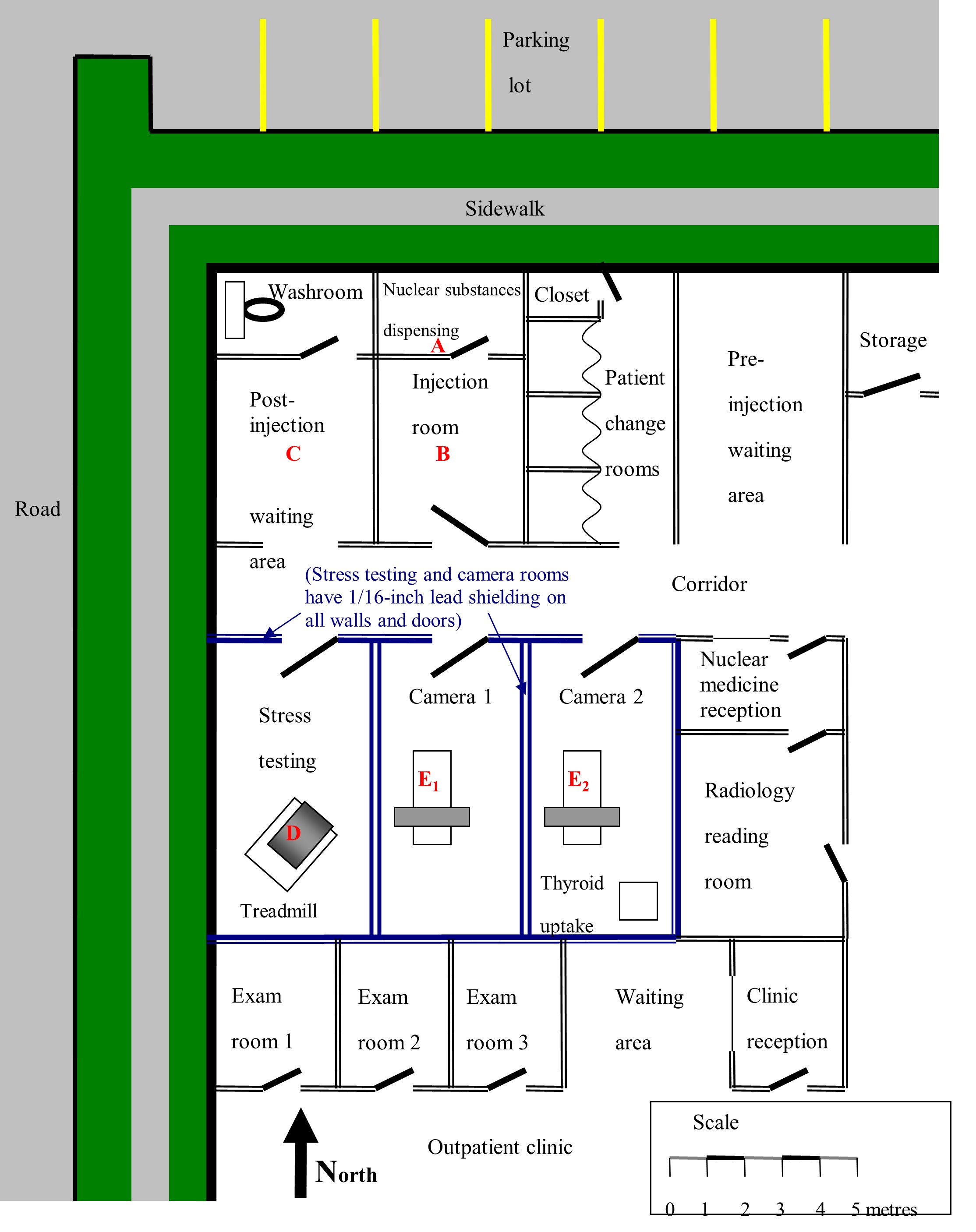
Obtain architectural drawings or make an accurate, scaled and dimensioned drawing of the facility and surrounding areas. The drawings need to show the locations where significant quantities of nuclear substances will be present. They will also show occupied locations where persons might be exposed to radiation as a result of licensed activity. If available, scaled architectural drawings are ideal for this purpose.
Identify the locations where nuclear substances are to be used. This includes rooms where nuclear substances will be administered to the patient and the main post-administration locations.
Figure A1 shows a hypothetical nuclear medicine department layout, with dimensions and basic shielding details. Letters A to E2 identify the locations with the greatest potential for exposure. The same method used to estimate radiation dose to these areas can be used for other areas, such as designated waiting areas, reception areas, changing rooms or washrooms.
Step (2) Estimating workload
The workload needs to be identified for each key location. Workload refers to the number of procedures per year, as well as the typical activity (MBq) per procedure.
For any given nuclear medicine facility, several different gamma-emitting nuclear substances may be used regularly and be present at a number of locations within the facility (e.g., Ga‑67, Ra-223, , Sr-89, Lu-177, Tc‑99m, In-111, I‑123, I‑131 and Tl‑201). Most of these nuclear substances emit several gamma rays of different energies which are attenuated to varying degrees in any shielding material.
Initially, all possible procedures are considered. If it can be demonstrated that some procedures are insignificant to the total doses incurred, the doses from such procedures may not require detailed estimates.
This can be determined by multiplying the typical activity for a procedure by the number of annual procedures of that type and by exposure duration per procedure.
Example:
For illustrative purposes, assume that the nuclear medicine department shown in figure A1 primarily performs three types of outpatient diagnostic procedures: cardiac imaging, bone scan and thyroid uptake. The typical daily workload and details of the nuclear substances and activities used are presented in table A2. The annual number of procedures performed is estimated from the daily workload by assuming five days of operation per week (no procedures are done on the weekends), 50 weeks per year.
| Procedure | Nuclear substance | Number of patients (N) | Average procedure duration | Average activity per treatment | (No. of proc.) x (Duration) x (Activity) | |
|---|---|---|---|---|---|---|
| Per day | Per year | |||||
| Cardiac imaging | Tc-99m | 7 | 1750 | 1.5 hrs * | 370 MBq (rest)* 1100 MBq (stress)* | 377,708 MBq‑h* 1,764,583 MBq‑h* |
| Bone scan | Tc-99m | 5 | 1250 | 0.75 hr | 800 MBq | 750,000 MBq‑h |
| Thyroid uptake | I-131 | 1 | 250 | 0.5 hr | 0.37 MBq | 46.3 MBq‑h |
* Assumes 35 minutes for rest test and 55 minutes for stress test (90 minutes total, or 1 ½ hours)
From this, it is clear that the radiation doses incurred by staff or the general public as a result of thyroid uptake procedures are likely to be negligible in comparison with cardiac analyses or bone scans and can be omitted from the dose estimation.
Step (3) Estimating occupancy factor
Identify the purpose, type of occupancy and occupancy factor of those areas within or in the immediate vicinity of the nuclear medicine department that will be occupied while nuclear substances are in use. These are the areas in which staff and the general public (other than the patient) would be expected to receive a radiation dose as a consequence of the nuclear medicine activities. For each area, determine:
- what the area is used for (e.g., reception desk, waiting room, radiopharmaceutical injection rooms, gamma camera room, washroom)
- who is normally present in the area (e.g., staff who are NEWs, non-NEWs performing work or members of the general public, such as persons accompanying patients or hospital staff performing work unrelated to the licensed activity)
- the occupancy factor (T) for each location and exposed group (e.g., the fraction of time a person spends in an area during which a radiation field is present)
The occupancy factor (T) should be determined for each location and exposed group (i.e., the fraction of total time during which a radiation field may be present at a particular location, for which another individual may be present at that location). When evaluating T, an important consideration is whether or not a person may be at the location of interest while there is a radiation field present in that area. For example, a technologist will be in many different locations throughout the course of a normal workday, but will always be in close proximity to the patient when injecting radiopharmaceuticals or while setting them up on the scanner bed. Conversely, cleaning staff may only be in the nuclear medicine department after normal operating hours, and consequently, may be exposed to little or no radiation despite spending appreciable lengths of time in the department.
For additional information, refer to the National Council on Radiation Protection and Measurements (NCRP) Report No. 151: Structural Shielding Design and Evaluation for Megavoltage X‑ and Gamma‑Ray Radiotherapy Facilities Footnote 7.
The determination of occupancy is probably the most difficult aspect of the dose assessment. To begin, you must first determine who (other than the patient) is exposed to radiation as a consequence of the operation of the nuclear medicine department. For nuclear medicine operations, these persons are normally divided into three categories: NEWs, non-NEWs and members of the public (including staff performing work unrelated to the licensed activity).
Generally, when calculating dose estimates, nuclear medicine technologists, radiologists and any other technical staff working in the department will be identified as NEWs.
Non-NEWs are staff members performing work related to the licensed activity with annual doses below 1 mSv.
Members of the public generally fall into three very broad groups:
- persons accompanying patients undergoing nuclear medicine scans
- persons who may be present in adjacent corridors or rooms, including pedestrians outside the building, patients in adjacent areas of the building (e.g., the outpatient clinic) and persons occupying areas above and below the department
- non-NEW staff performing work/duties unrelated to the licensed activity (e.g., porters, nurses, couriers)
Trying to assess the doses received by every individual from every possible source is clearly impractical, so the second step is to simplify the problem. This can be done by evaluating the proximity, frequency and duration of exposure of persons in each group to identify the most exposed persons. Then, you need only evaluate these “worst case” exposures within each group, because it can be safely assumed that all other persons in each group receive lesser doses.
The final stage of the occupancy review is to determine where and how long. That is:
- Where are the nuclear substances present and for how long?
- Where are the most exposed individuals present and for how long?
Implicit in this part of the evaluation is that only the locations that will contribute significantly to the doses incurred need to be considered. For instance, consider a nuclear medicine technologist working with a patient on the treadmill in the stress-testing room in figure A1. At the same time, the technologist will be receiving some radiation dose from injected patients who may be present in camera rooms 1 and 2 or the post-injection waiting area. However, because of the longer distances between the technologist and these sources of exposure and the intervening shielding, these doses will be negligibly small in comparison with the dose received from the patient on the treadmill. Thus, while the technologist is in the stress-testing room, only the dose received from the patient on the treadmill needs to be evaluated.
Example:
For the purpose of the example, the following assumptions have been made:
- All work is shared equally between three nuclear medicine technologists. In comparison with the technologists, radiologists are present in the department only periodically, for relatively short periods of time and with minimal direct exposure to injected patients or radiopharmaceuticals.
- There are one or more full-time receptionists for the nuclear medicine department who spend essentially all of their time in the reception office. The same is true for the adjacent outpatient clinic.
- Other ancillary staff, such as porters and cleaning and maintenance staff, are present only infrequently, with restricted access to areas in which nuclear substances are used and with minimal direct exposure to injected patients or radiopharmaceuticals.
- Family members accompanying patients who are undergoing nuclear medicine procedures are present only for a few hours per year.
- Physicians working in the adjacent outpatient clinic spend approximately one half of their time in the examining rooms immediately adjacent to the camera suites and the stress-testing room.
- The clinic is a single-story building, built on grade, so there is no occupancy below and very minimal occupancy above (e.g., during roof repairs).
From these assumptions and the facility layout given in figure A1, it is reasonable to expect that:
- The nuclear medicine technologists are the most exposed persons amongst the NEWs, and since the work is divided equally among them, the doses they receive should be very similar.
- The receptionists in the nuclear medicine department and the physicians performing work related to the licensed activity in the adjacent rooms are likely to receive the highest non-NEW occupational exposures due to their lengthy exposure times and relatively close proximity to the camera and stress-testing rooms.
- Members of the public (other than the patients themselves) should receive doses well below those received by the receptionists and/or physicians, but staff performing work unrelated to the licensed activity whose offices are in near proximity (beside or above/below the nuclear medicine department) will receive the highest doses among the individuals in this category.
Therefore, doses need to be estimated for only three representative individuals: a nuclear medicine technologist, a nuclear medicine receptionist and a physician performing work unrelated to the licensed activity in the adjacent outpatient clinic.
| Persons exposed | NEW | Important location(s) occupied | Source location(s) making significant contribution to dose | Occupancy factor (T) | Rationale/comment |
|---|---|---|---|---|---|
| Nuclear medicine technologist | Yes | Dispensing | A | 1/3 | An occupancy factor of ⅓ is applied to each location because the total number of procedures performed is split equally between three technologists. Although procedures will be split between camera rooms 1 and 2, when evaluating the dose to a technologist, it can be assumed that all of the procedures are performed in one room, since this will not alter the total dose received by the technologist. |
| Injection | B | ||||
| Stress-testing | D | ||||
| Camera 1 or Camera 2 | E1 or E2 | ||||
| Receptionist | No | Nuclear medicine reception | A, B and C | 1 | An occupancy factor of 1 is used because it is assumed that the receptionist remains in the reception area for the entire workday. The contributions from source locations A, B and C are evaluated because there is no shielding between these source locations and the reception area. The contribution from E2 is evaluated because it is immediately adjacent to the reception area. D and E1 can probably be omitted because the radiation that injected patients emit in these rooms must pass through multiple shielded walls to reach the reception area. However, it is prudent to evaluate E1 to confirm that the dose contribution from this point to the reception area will be negligible. |
| E2 | |||||
| E1 (see comments) | |||||
| Physician in adjacent clinic | No | Exam room 2 | D, E1 or E2 | 1/2 | An occupancy factor of ½ is used because the example states that each physician spends approximately ½ of their time in the exam rooms. A physician may be present in any of exam rooms 1, 2 or 3. The central room, exam 2, is reasonably representative of their average location. Source locations A, B and C are distant from the exam rooms and are doubly shielded by the lead lining of the intervening stress-testing and camera rooms; thus, they will make a negligibly small contribution to the dose in comparison with source locations D, E1 and E2. |
Step (4) Dose rate calculations
Radiation dose rate calculations should be made for each potentially occupied area. There are two basic methods of estimating the radiation dose rates to which staff and the general public (excluding the patient) will be exposed as a result of typical nuclear medicine operations.
The first method is to take direct measurements of the dose rates in surrounding areas using a sufficiently sensitive, properly calibrated radiation survey meter. The type, model, energy range and energy response of the dose rate meter to be used should be provided. Because dose rates in the surrounding rooms and areas are typically very low, the survey meter used should have a scaler function to allow for long counting times (e.g., 10 minutes or more) to reduce uncertainty in the measurement. Background radiation is to be subtracted from the measured target dose rate. The background dose rate measurement should be made with the same long counting time in an area or room that is physically isolated and at a distance from any nuclear substances. This method is generally useful when evaluating an existing department or when conducting a comparative analysis for designing a new room or department that is similar in layout and design to an existing site. It is particularly useful when an applicant needs to analyze the impact of proposed changes, such as increased workload or changes to the facility layout.
Measurements can be performed after normal operating hours by placing source vials that contain the typical average quantities of the appropriate nuclear substances at representative locations (e.g., the centre of the scanning bed to represent a patient undergoing a scan). Alternatively, sample measurements could simply be taken at each location over the course of a typical working day. In either case, care must be taken to ensure that the activities and nuclear substances being used when the measurements are taken are truly representative of normal operating conditions, when an average is taken over a suitably representative timeframe (e.g., daily, weekly, yearly). It is also important to stress that in many cases, very low dose rates (just barely above background) need to be measured in order to ascertain annual doses. In such cases, dose rate meters with integrated counting must be employed in order to capture statistically significant data. The lower the dose rate, the longer the integration time should be. The applicant should aim for ten-minute integration times for very low dose rates, always making sure to subtract the background values, which should be captured using the same integration time.
The second method is a mathematical approach that relies on the known physical properties of the nuclear substances being used, the distances to each occupied area and the shielding properties and thickness of the building materials. As such, it is generally useful when designing a new room or department.
The following is a general formula for performing dose rate calculations.
Equation 1:
if t is thicker than TVL1, then:
Where:
| R | is the dose rate produced by nuclear substance at location | (mSv h-1) |
| Γ | is the specific gamma ray constant for nuclear substance | (mSv h-1 MBq‑1 m2) |
| A | is the activity of nuclear substance | (MBq) |
| d | is the distance between nuclear substance and location | (m) |
| t | is the thickness of shielding material in any shielded barrier between nuclear substance and location | (mm) |
| TVL (1&2) | is the first and second tenth-value layer (TVL) thicknesses of material for a given nuclear substance (i.e., the thickness of material that would be required to reduce the photon radiation dose rate produced by the nuclear substance to 1/10 of its initial value for the first tenth-value layer and a subsequent 1/10 of its value for the second tenth-value layer) | (mm) |
Specific gamma ray constants are defined in terms of the dose rate (e.g., mSv h-1) at one metre from the source (m2), per unit of source activity (e.g., MBq-1), but the exact units used may vary between different references. When performing dose rate calculations, care must be taken to ensure the consistency of units between R, Γ and A. For consistency, the CNSC has published the Radionuclide Information Booklet (RIB) Footnote 8, which provides dose rate constants, half- and tenth-value layers, as well as other useful information for a variety of commonly used nuclides. Note that the CNSC RIB provides first and second half- and tenth-value layers; using both will yield more accurate results than using the first layer only, especially for poly-energetic nuclides. The RIB also provides an Excel formula for calculating dose rates using the first and second half- and tenth-value layers. For simplicity, the examples below show the calculation using the first tenth-value layer only.
Example:
Table A5 on the following page summarizes the parameters required to perform the dose rate estimates for this example. The distances d were measured directly from figure A1 for the nuclear medicine reception area and exam room 2. To calculate doses to the nuclear medicine technologists, their proximity to the patient when performing diagnostic procedures was estimated based on internal room dimensions and typical work procedures. Lead thicknesses are based on the assumption that all interior walls of the stress-testing room, camera room 1 and camera room 2 are lined with 1/16-inch (1.6 mm) lead.
All other interior walls are assumed to be constructed of ordinary drywall (gypsum board) and to provide minimal attenuation.
The last column of table A5 lists the calculated dose rates at each location for each of the exposed groups considered, for bone scan and cardiac stress-testing procedures. A sample calculation for one representative source location (E2), exposure group (receptionist) and procedure (cardiac stress-testing, stress component) is given below:
| Nuclear substance | Tc-99m |
|---|---|
| Γ | 1.853E-5mSv h‑1 MBq‑1 m2 |
| TVL1/TVL2 | 1.1 mm/1.0 mm |
| Total activity A used for the procedure (by the stress-testing stage, patient has already been given both the rest injection of 370 MBq and the stress injection of 1100 MBq) | 1470 MBq |
| Thickness t of lead shielding in wall between camera 2 and nuclear medicine reception | 1.6 mm (1/16 inch) |
| Distance d from patient on bed of camera 2 and nuclear medicine reception (from figure A1) | 5 metres |
Using equation 1:
For simplicity, there was no correction for the decay of Tc-99m in this calculation. While decay will cause some reduction in the calculated dose rate, the reduction will be relatively small. For example, if the procedure lasts 1.5 hours, the initial rest injection will have decayed to the following, which is still 84% of its initial value, by the end of the procedure:
In the context of the requirement to keep radiation doses ALARA, corrections of this magnitude are unlikely to be the difference between an acceptable or unacceptable design. However, applicants may choose to explicitly account for decay in their design analysis.
| Persons exposed | NEW | Occupied location | Source location | Distance d (m) | Lead thickness t (mm) | Activity A (MBq) which may temporarily be present at each source location due to each procedure | Dose rate R (mSv h-1) at occupied location while source activity A is present at each source location | ||||
| Cardiac (rest) | Cardiac (stress) | Bone scan | Cardiac (rest) | Cardiac (stress) | Bone scan | ||||||
| Nuclear medicine technologist | Yes | Dispensing | A | 0.75 | 0 | 370 | 1100 | 800 | 1.2 x 10⁻² | 3.6 x 10⁻² | 2.6 x 10⁻² |
| Injecting | B | 0.75 | 0 | 370 | 1470 | 800 | 1.2 x 10⁻² | 4.8 x 10⁻² | 2.6 x 10⁻² | ||
| Stress-testing | D | 3 | 0 | N/A | 1470 | N/A | N/A | 3.0 x 10⁻³ | N/A | ||
| Camera 1 or camera 2 | E1 or E2 | 3 | 0 | 370 | 1470 | 800 | 7.6 x 10⁻⁴ | 3.0 x 10⁻³ | 1.6 x 10⁻³ | ||
| Receptionist | No | Nuclear medicine reception | A | 13 | 0 | 370 | 1100 | 800 | 4.1 x 10⁻⁵ | 1.2 x 10⁻⁴ | 8.8 x 10⁻⁵ |
| B | 10 | 0 | 370 | 1100 | 800 | 6.9 x 10⁻⁵ | 2.0 x 10⁻⁴ | 1.5 x 10⁻⁴ | |||
| C | 13 | 0 | 370 | 1470 | 800 | 4.1 x 10⁻⁵ | 1.6 x 10⁻⁴ | 8.8 x 10⁻⁵ | |||
| E2 | 5 | 1.6 | 370 | 1470 | 800 | 8.7 x 10⁻⁶ | 3.4 x 10⁻⁵ | 1.9 x 10⁻⁵ | |||
| E1 | 9 | 4.8 | 370 | 1470 | 800 | 1.7 x 10⁻⁹ | 6.7 x 10⁻⁹ | 3.7 x 10⁻⁹ | |||
| Physician in adjacent clinic | No | Exam room 2 | D | 5 | 1.6 | N/A | 1470 | N/A | N/A | 3.4 x 10⁻⁵ | N/A |
| E1 | 5 | 1.6 | 370 | 1470 | 800 | 8.7 x 10⁻⁶ | 3.4 x 10⁻⁵ | 1.9 x 10⁻⁵ | |||
| E2 | 7 | 1.6 | 370 | 1470 | 800 | 4.4 x 10⁻⁶ | 1.8 x 10⁻⁵ | 9.6 x 10⁻⁶ | |||
Step (5) Annual dose rate calculations
Patients typically occupy several different locations over the course of the nuclear medicine procedure and may contribute to the dose received by a person occupying a single location (e.g., the dose from patients in the injection room, scanner rooms and post-injection waiting areas may all contribute to the dose received by the receptionist at the front desk). Exposed persons may also occupy several different areas over the course of any given day, some of which may contribute far more significantly to the total radiation dose they receive.
Once the dose rate in each occupied area – generated by each combination of procedure, source location and occupancy factor – has been either calculated or measured, the resulting annual dose received by persons in that area can be estimated by multiplying the dose rate by the total exposure duration per year.
For a given combination of procedure, source location, occupied location and exposed person, the total exposure duration per year is given by the product of: the total number of procedures performed per year (N, see table A2); the occupancy factor for the exposed person and occupied location (T, see table A2); the dose rate (R, see table A5); and the duration of time (S) the source/injected patient is present at the designated source location (in hours). The annual dose (D) is then:
Equation 2:
Example:
Table A6 summarizes the parameters required to estimate the dose rate for the example. Estimated total procedure times were given in table A2. These are broken down into the approximate times the source/patient spends at each key location (S) in table A6.
For example, cardiac stress-testing was estimated to require 1.5 hours.
This has been divided into:
| 2 minutes for the test injection | 0.033 h |
| 20 minutes in the post-injection waiting room | 0.33 h |
| 15 minutes scanning in either camera room | 0.25 h |
| 2 minutes for the stress test injection | 0.033 h |
| 20 minutes in the waiting room | 0.33 h |
| 15 minutes in the treadmill room | 0.25 h |
| 15 minutes scanning in either camera room | 0.25 h |
| Total: | 1.48 h |
The last column of table A6 lists the calculated annual doses at each location, for each of the exposed groups considered, for both the bone scan and cardiac stress-testing procedures. A sample calculation for one representative source location (E2), exposure group (receptionist) and procedure (cardiac stress-testing, stress component) is given below:
N | 1750 procedures per year (1750 y-1) |
T | 1 |
R | 3.8 × 10⁻⁵ mSvh-1 |
S | 0.25 hr |
Using equation 2:
| D | = N × T × R × S |
| Dcamera 2, reception | = 1750 y-1 × 1 × 3.8 × 10-5 mSv h-1 × 0.25 hr = 1.66 × 10⁻² mSv |
Explicit calculations of the dose a nuclear medicine receptionist would receive as a result of scans in camera room 1 have been dropped, since it is clearly demonstrated in table A5 that the dose rate in nuclear medicine reception due to patients in camera room 1 will be trivially small (< 1 nSv h-1). When calculating the annual dose to a nuclear medicine receptionist and to a physician in the adjacent outpatient clinic, the total scanning workload, including both cardiac stress-testing and bone scans, is presumed to be split evenly between camera rooms 1 and 2. The total doses listed are the sum of each of the doses from the individual procedures for each of the exposed persons.
A few interesting aspects about the calculated doses should be mentioned. First, note that 60% of the nuclear medicine technologists’ dose is estimated to be received in the relatively short periods of time they spend either directly handling the Tc-99m or in very close proximity to the patient while delivering the injection. This suggests that when examining operating procedures with the aim of keeping doses ALARA, improvements to these procedures are likely to have the greatest benefit.
Similarly, the receptionist at this hypothetical clinic potentially receives the greatest dose from injected patients waiting to be scanned, despite having a designated “hot” patient waiting area well removed from the reception desk. If dose reduction were deemed to be necessary, adding shielding to the east wall of the injected-patient waiting area could be considered.
Finally, note that despite the extended periods of time physicians in the adjacent outpatient clinic spent in the examining rooms located very close to the scanning rooms, their doses are negligibly small due to the shielding incorporated into the walls of the scanning rooms.
| Persons exposed | Occupied location | Source location | Number of procedures N | T | Duration of time S (h) the source/patient is present at each location per procedure | Dose rate R (mSv h-1) at the occupied location while source/patient present at each source location | Annual dose D (mSv) at the occupied location | ||||||||
|---|---|---|---|---|---|---|---|---|---|---|---|---|---|---|---|
| Card. (rest) | Card. stress) | Bone scan | Card. (rest) | Card. (stress) | Bone scan | Cardiac (rest) | Cardiac (stress) | Bone scan | Card (rest) | Card. (stress) | Bone scan | ||||
| Nuclear medicine technologist | Dispensing | A | 1750 | 1750 | 1250 | 1/3 | 0.008 | 0.008 | 0.008 | 1.2 x 10⁻² | 3.6 x 10⁻² | 2.6 x 10⁻² | 0.0569 | 0.1691 | 0.0878 |
| Injection | B | 1750 | 1750 | 1250 | 1/3 | 0.033 | 0.033 | 0.033 | 1.2 x 10⁻² | 4.8 x 10⁻² | 2.6 x 10⁻² | 0.2346 | 0.9322 | 0.3624 | |
| Stress-testing | D | N/A | 1750 | N/A | 1/3 | N/A | 0.25 | N/A | N/A | 3.0 x 10⁻³ | N/A | N/A | .4414 | N/A | |
| Camera 1 or camera 2 | E1 or E2 | 1750 | 1750 | 1250 | 1/3 | 0.25 | 0.25 | 0.33 | 7.6 x 10⁻⁴ | 3.0 x 10⁻³ | 1.6 x 10⁻³ | 0.1111 | 0.4414 | 0.2265 | |
| Total annual dose received by each nuclear medicine technologist | 3.0633 mSv | ||||||||||||||
| Receptionist | Nuclear medicine reception | A | 1750 | 1750 | 1250 | 1 | 0.008 | 0.008 | 0.008 | 4.1 x 10⁻⁵ | 1.2 x 10⁻⁴ | 8.8 x 10⁻⁵ | 0.0006 | 0.0017 | 0.0009 |
| B | 1750 | 1750 | 1250 | 1 | 0.033 | 0.033 | 0.033 | 6.9 x 10⁻⁵ | 2.0 x 10⁻⁴ | 1.5 x 10⁻⁴ | 0.0040 | 0.0118 | 0.0061 | ||
| C | 1750 | 1750 | 1250 | 1 | 0.33 | 0.33 | 0.33 | 4.1 x 10⁻⁵ | 1.6 x 10⁻⁴ | 8.8 x 10⁻⁵ | 0.0234 | 0.0931 | 0.0362 | ||
| E2 | 875 | 875 | 675 | 1 | 0.25 | 0.25 | 0.33 | 8.7 x 10⁻⁶ | 3.4 x 10⁻⁵ | 1.9 x 10⁻⁵ | 0.0019 | 0.0075 | 0.0042 | ||
| Total annual dose received by each receptionist | 0.19132 mSv | ||||||||||||||
| Physician in adjacent clinic | Exam room 2 | D | N/A | 1750 | N/A | 1/2 | N/A | 0.25 | N/A | N/A | 3.4 x 10⁻⁵ | N/A | N/A | 0.0075 | N/A |
| E1 | 875 | 875 | 625 | 1/2 | 0.25 | 0.25 | 0.33 | 8.7 x 10⁻⁶ | 3.4 x 10⁻⁵ | 1.9 x 10⁻⁵ | 0.0009 | 0.0038 | 0.0019 | ||
| E2 | 875 | 875 | 625 | 1/2 | 0.25 | 0.25 | 0.33 | 4.4 x 10⁻⁶ | 1.8 x 10⁻⁵ | 9.6 x 10⁻⁶ | 0.0005 | 0.0019 | 0.0010 | ||
| Total annual dose received by each physician working in the adjacent outpatient clinic | 0. 0176 mSv | ||||||||||||||
Conclusion
The annual dose to the receptionist and reception area, assuming 100% occupancy, is less than 200 µSv. The annual dose to the physician in the adjacent clinic is less than 20 µSv.
To complete the dose assessment, the annual doses are estimated for other staff and members of the general public, other than the patient, who are in and around the nuclear medicine rooms at the facility. The CNSC may consider that an ALARA assessment is not required when individual occupational doses are unlikely to exceed 1 mSv per year, when the dose to individual members of the public is unlikely to exceed 50 µSv per year, and when the annual collective dose (both occupational and public) is unlikely to exceed 1 person‑Sv (as recommended in REGDOC-2.7.1, Radiation Protection, as amended from time to time) Footnote 4.
Shielding calculations for positron emitting nuclear substances
The basic approach to shielding calculations for positron emitting nuclear substances or any other high-energy gamma-emitting nuclear substance, such as I-131, is similar to that for conventional diagnostic nuclear medicine, as outlined in the previous example. The only significant difference is the thickness of shielding required due to higher energies. In such cases, the use of lead may be impractical due to weight and structural considerations. Concrete, either in poured slabs or one solid block, is generally a more viable solution to positron emitting nuclear substances shielding issues.
To illustrate this, consider the previous example in which 1/16-inch (1.6 mm) lead shielding was used to line the camera rooms. For Tc-99m, which emits 141 keV gamma rays, this equates to 1.6 mm/1.1 mm = 1.45 tenth-value layers of shielding, which reduces the radiation dose rates and corresponding doses in surrounding areas to 3.5% of their unshielded values.
By contrast, positron emitting nuclear substances all decay via positron emission and thus emit two 511 keV annihilation gammas per decay. At this energy, the first TVLs for lead and concrete are approximately 17 mm and 24 cm, respectively. Note that because positron emitting nuclear substances all emit gammas at the same energy, the TVLs do not change from nuclear substance to nuclear substance. To achieve the same degree of attenuation for positron emitting nuclear substances would therefore require 1.45 x 17 mm = 24.6 mm of lead, or 1.45 x 24 cm = 34.8 cm of concrete.
In such cases, the use of lead becomes impractical because of weight and structural considerations. For example, an 8-foot by 12-foot wall of lead 30 mm thick would weigh 3000 kg and would require a structural support wall capable of retaining this load. Thus, concrete – either in poured slabs or as a solid concrete block – is a much more viable solution to positron emitting nuclear substances shielding problems. The heavy shielding requirements for positron emitting nuclear substances make it difficult to retrofit an existing room to accommodate a PET scanner.
The periodical Medical Physics (33, 1; January 2006) provides useful technical information and guidance on shielding requirements and dose estimates specifically related to positron emitting nuclear substances operations Footnote 9.
Shielding calculations for in-patient I-131 therapy
There is very little difference between the shielding calculations for conventional diagnostic nuclear medicine and for in-patient nuclear medicine therapy treatments, such as I-131 thyroid cancer treatment. The patient location is essentially fixed inside what is usually a dedicated treatment room on one of the wards. The primary occupationally-exposed group to be considered is the nursing staff attending to the patients while they are in hospital. Doses to members of the general public in adjacent rooms must also be considered.
As a condition of the licence, the design must be such that the dose rate in occupied areas around the treated patient’s room does not exceed 2.5 µSv/h or that other patients do not receive a dose in excess of 500 µSv per hospital stay.
For these room classifications, dose estimates are required. The same approach may be followed as described in Step (4) Dose rate calculations. The results will be conservative as both the thyroidal and extra-thyroidal biological half-lives would not be considered using this approach. Applicants are free to use more refined dose calculations for I-131 therapies by applying the appropriate uptake fraction and biological half-lives to consider the doses from the thyroidal and extra-thyroidal components of the patient separately. A good reference for such calculations is: Journal of Nuclear Medicine, November 2000, 41 (11) 1868-1875.
Calculating dose rate and doses outside of hot cells
Licensees involved in the production of nuclear substances and/or the chemical processing of those nuclear substances into radiopharmaceuticals must be equipped to handle much greater quantities of nuclear substances than nuclear medicine departments or research laboratories can handle. Typically, they will have one or more heavily shielded hot cells in which processing activities are performed with remote manipulators that enable staff to safely perform any required handling of the nuclear substances. Hot cells are normally sealed when in use to prevent volatile, gaseous or fine-particulate radioactive material from contaminating the lab. In addition, they will normally have a dedicated ventilation system, with filters to minimize any such releases to the external environment. Hot cells are equipped with manipulators for the remote handling of objects inside the hot cell. This prevents extremity doses and reduces the risk of spills.
A typical hot cell might be roughly 2 m high, 1.5 m wide and 1 m deep, and shielded with 75 mm of lead (Pb) encased in steel. This provides ~5 TVLs of shielding against positron emitting nuclear substances. For further information on TVLs for commonly used nuclear substances, see the CNSC’s Radionuclide Information Booklet Footnote 8.
Two typical hot cells with manipulators are shown below:
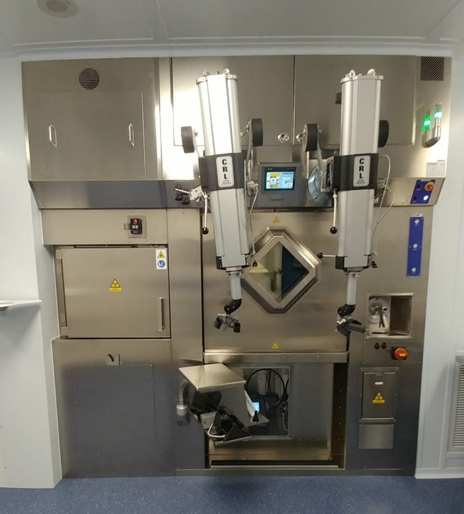
Both hot cells shown have 7.5 cm lead shielding in the walls, floor and ceiling. The lead glass windows are 18 cm thick and have a lead equivalence of 7.5 cm (courtesy of University of Ottawa Heart Institute).
The five-step dose calculation method described previously can easily be extended to estimate the doses incurred by staff performing work using the hot cells:
Step (1) Prepare a reasonably accurate, dimensioned sketch of the facility and surrounding areas.
The following diagram is used for the purpose of this example.
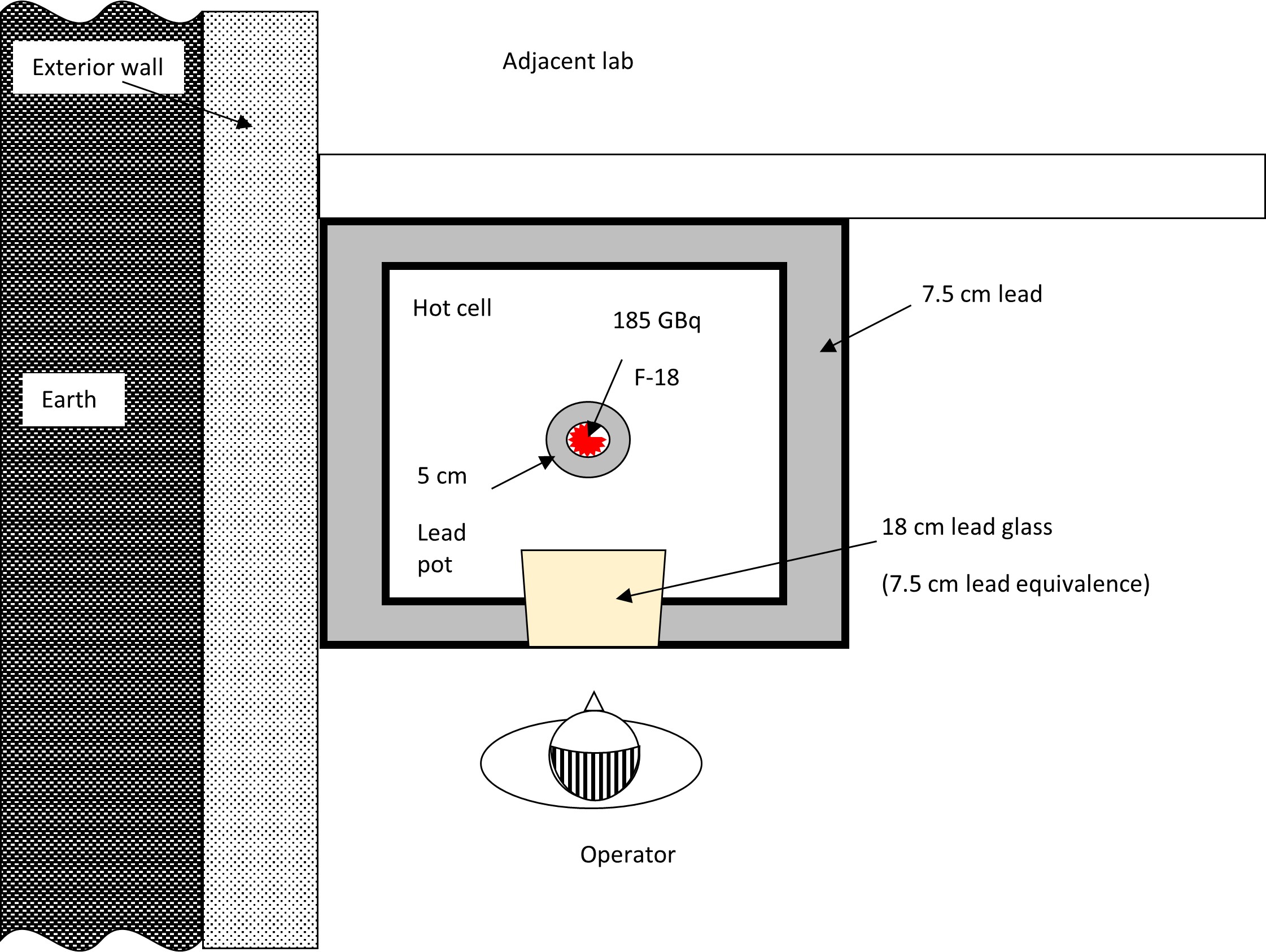
Step (2) Identify the key locations where radioactive materials are to be used and the workload for each of these locations.
- F-18, 185 GBq (5Ci) produced per run
- F-18 is present in hot cell for one hour
- Assume one production run of F-18 per day x 250 operating days per year
Step (3) Identify the purpose, type of occupancy and occupancy factor of areas where nuclear substances are used, and areas in the direct vicinity of where nuclear substances are used.
- Restricted access area (NEWs only)
- Operator at manipulators for ⅓ hour per run
- Occupancy of adjacent lab is intermittent, T = ½
Step (4) Estimate the radiation dose rates in each potentially occupied area.
Equation 1
If t is thicker than TVL1, then:
Where:
| R | is the dose rate (μSv h-1) produced by F-18 at each location |
| Γ | 0.1398 μSv h-1 MBq-1 m2 |
| A | 185,000 MBq |
| d | Assume operator is 1 m from source |
| t | 75 mm Pb equivalent in walls/window/floor of hot cell (plus, 50 mm Pb in walls and bottom of Pb pot containing F-18, but top is open and is visible from the operator position) |
| TVL1 | 17 mm |
| TVL2 | 14 mm |
Therefore, outside the hot cell at one metre from the F-18, the dose rate is:
R = (0.1398 μSv h-1 MBq-1 m2) x (185,000 MBq) x 0.1 x 10-((125-17)/14)
R = 0.00005 µSv h-1, which is effectively ZERO
Direct line of sight between the operator and the product should also be considered by excluding the lead pot shielding:
R = (0.1398 μSv h-1 MBq-1 m2) x (185,000 MBq) x 0.1 x 10-((75-17)/14)
R = 0.186 or for simplicity, ≈ 0.2 µSv h-1
Step (5) Extrapolate the calculated dose rates to annual doses.
Worst-case exposure assumes no lead pot. Ignoring decay over the exposure duration:
Operator dose = 250 days/y x 1/3 h/day x 0.2 µSv h-1 or ≈ 17 µSv y-1
Lab staff dose = (250 days/y x 0.5 h/day x 0.2 µSv h-1)/(3m)2 ≈ 3 µSv y-1
Thus, for the parameters assumed in the example, the shielding in the hot cell is more than adequate. This is in fact the case for typical automated positron emitting nuclear substances processing operations. The majority of staff’s dose generally comes from handling the quality control (QC) samples once they have been dispensed and extracted from the hot cell. The approach to QC dose calculation is effectively the same as that for nuclear medicine dispensing and injection operations in the previous dose calculation example.
Appendix B: Summary of Requirements and Guidance for Design Assessment Forms
The following table “Summary of requirements and guidance for the DAFs” provides an overview of requirements and guidance applicable to the various room classifications. An application must indicate if the requirements are met or provide an alternative approach for meeting the intent of the requirements. Any alternative approach for meeting the intent of the requirements shall demonstrate that the ALARA principle is maintained.
There are 7 DAF forms:
- Intermediate-Level Room
- High-Level Room
- Containment-Level Room
- Nuclear Medicine– Radiopharmacy (≤ 50 ALI)
- Nuclear Medicine – Radiopharmacy (≤ 500 ALI)
- Nuclear Medicine – Radiopharmacy (> 500 ALI)
- Nuclear Medicine – Other
Summary of Requirements and Guidance for the DAFs | |||||||
Dose estimates | Design assessment form requirement (R) or guidance (G) | ||||||
Intermediate | High | Containment | Nuclear medicine (NM) – | NM –Radiopharmacy | NM –Radiopharmacy | NM – | |
| Include detailed dose estimates including assumptions. It is also suggested to include a schematic of the room to assist in the review of the assumptions and calculations. | N/A | R | R | R | R | R | R |
| Section B – Finishing and fixtures | ||||||||
| Design assessment form requirement (R) or guidance (G) | ||||||||
| Design feature | Intermediate | High | Containment | Nuclear medicine (NM) – Radiopharmacy ≤ 50 ALI | NM –Radiopharmacy ≤ 500 ALI | NM –Radiopharmacy > 500 ALI | NM – Other | |
| B1 | Use flooring, work surfaces, chairs, cupboards and shelving that have a smooth, impervious and washable finish in areas where unsealed nuclear substances are used. | R | R | R | R | R | R | R |
| B2 | Flooring should have a 1-piece design. If the flooring is more than 1 piece, all joints in the flooring material should be sealed. The joint between the flooring and the walls should be rounded to prevent spills from getting underneath them. Flooring should have a strippable coating to make decontamination easier should an accident occur. | G | G | G | G | G | G | G |
| B3 | All joints on work surfaces, including bench tops, should either be sealed or have a seamless 1-piece design. | G | G | G | G | G | G | G |
| B4 | Countertops should include a lip or raised edge to prevent runoff onto the floor. If the countertop abuts a wall, the joint should also be rounded or the countertop should have a backsplash. | G | G | G | G | G | G | G |
| B5 | Walls should be finished with a smooth and washable surface, and all joints should be sealed. This can make cleanup easier if a room is contaminated by back-spray from a vial or some other similar event occurs. | G | G | G | G | G | G | G |
| B6 | The ceiling should be finished with a smooth, washable surface, and all the joints should be sealed. Easily replaceable modular ceilings (e.g., drop ceiling with tiles) are also acceptable. | G | G | G | G | G | G | G |
| Section C – Emergency facilities and general contamination control considerations | ||||||||
| Design feature | Design assessment form requirement (R) or guidance (G) | |||||||
| Intermediate | High | Containment | Nuclear medicine (NM) – Radiopharmacy ≤ 50 ALI | NM –Radiopharmacy ≤ 500 ALI | NM –Radiopharmacy > 500 ALI | NM – Other | ||
| C1 | Areas for food and drink preparation, consumption or storage are not located inside any room in which unsealed nuclear substances are used. | R | R | R | R | R | R | R |
| C2 | Have personnel decontamination facilities appropriate to the activities and the nuclear substances and chemicals used. | N/A | R | R | N/A | R | R | N/A |
| C3 | Have emergency lighting. | N/A | R | R | N/A | R | R | N/A |
| C4 | An accessible area should be designated to store materials and equipment used for decontamination and monitoring. Materials and equipment should include spill kits, survey meters and contamination meters appropriate for the nuclear substances and chemicals being used. | G | G | G | G | G | G | G |
| C5 | Decontamination facilities should include a separate hand-washing sink near the entrance to the room. | G | G | G | G | G | G | G |
| C6 | An emergency eye-wash station and an emergency shower should be located in or near the room. | G | G | G | G | G | G | G |
| C7 | Personal contamination monitoring equipment suitable for the nuclear substances being used should be available at all points of entry/exit. | G | G | G | G | G | G | G |
| C8 | Amenities like coat hooks, active laundry bins, storage lockers, etc., should be provided in the room near the entrance. This can facilitate the removal and proper storage of potentially contaminated personal protective equipment, such as lab coats, before leaving the room. | G | G | G | G | G | G | G |
| C9 | Nuclear medicine departments should have washrooms dedicated for use by patients undergoing nuclear medicine procedures. | N/A | N/A | N/A | N/A | N/A | N/A | G |
| C10 | Due to the potential for contamination, if patients need to stay at the hospital after the radioisotope is administered, they should stay in a classified room. | N/A | N/A | N/A | N/A | N/A | N/A | G |
| Section D – Plumbing | ||||||||
| Design feature | Design assessment form requirement (R) or guidance (G) | |||||||
| Intermediate | High | Containment | Nuclear medicine (NM) – Radiopharmacy ≤ 50 ALI | NM –Radiopharmacy ≤ 500 ALI | NM – Radiopharmacy > 500 ALI | NM – Other | ||
| D1 | Where routine releases occur via the sewer, or where the potential for accidental releases exists, have mechanisms in place to ensure that these releases are ALARA and meet applicable clearance levels. | R | R | R | N/A | R | R | N/A |
| D2 | Each in-patient room shall have its own dedicated washroom. | N/A | N/A | N/A | N/A | N/A | N/A | R |
| D3 | Sinks should be made of material that is readily decontaminated. | G | G | G | G | G | G | G |
| D4 | Each sink should have an overflow outlet. | G | G | G | G | G | G | G |
| D5 | Faucets should be operable by a means that does not require direct hand contact. | G | G | G | G | G | G | G |
| D6 | Faucets with vacuum or cooling line attachments should include backflow protection devices. | G | G | G | G | G | G | G |
| D7 | Drains should be constructed of a corrosion-resistant material suitable for the chemicals used in the room. | G | G | G | G | G | G | G |
| D8 | Drains and sink traps that may contain transient quantities of nuclear substances must be marked accordingly and be clearly identified on any plans provided to maintenance personnel or contractors. | G | G | G | G | G | G | G |
Section E – Access control | ||||||||
Design feature | Design assessment form (requirement (R) or guidance (G) | |||||||
Intermediate | High | Containment | Nuclear medicine (NM) Radiopharmacy ≤ 50 ALI | NM –Radiopharmacy ≤ 500 ALI | NM – Radiopharmacy > 500 ALI | NM – Other | ||
E1 | Have an access control system (key, keypad, key fob, other) in place to ensure that only authorized workers can enter the restricted room. | R | R | R | R | R | R | R |
E2 | Ensure that rooms that give access to nuclear substances have lockable doors. | R | R | R | R | R | R | R |
E3 | Have a secondary lockable storage area (refrigerator, freezer, cupboard) for rooms that are shared with workers who are not authorized to use nuclear substances. The secondary storage container must be secured such that it cannot be easily removed from the room. | R | R | R | R | R | R | R |
E4 | Have clearly delineated designated areas where unsealed nuclear substances are used when an area in the room is also to be used for other types of work. | R | R | R | R | R | R | R |
E5 | Ensure that accessible windows are secure to prevent unauthorized access to the room. | R | R | R | R | R | R | R |
| Section F – External dose control | ||||||||
| Design feature | Design assessment form requirement (R) or guidance (G) | |||||||
| Intermediate | High | Containment | Nuclear medicine (NM) Radiopharmacy ≤ 50 ALI | NM –Radiopharmacy ≤ 500 ALI | NM – Radiopharmacy > 500 ALI | NM – Other | ||
| F1 | Include the dose estimates to nuclear energy workers (NEWs) and non-NEWs in the proposed room and adjacent areas. | N/A | R | R | R | R | R | R |
| F2 | Localized shielding should be used in areas where nuclear substances are to be used or stored. The extent of shielding depends on the quantities of nuclear substances that emit penetrating radiation. It may be necessary to reinforce surfaces to bear the weight of any shielding material required. | G | G | G | G | G | G | G |
| F3 | When appropriate, shielding should be incorporated into the structure of the room. | G | G | G | G | G | G | G |
| F4 | To minimize the movement of nuclear substances, areas between which nuclear substances are to be moved should be located as close to each other as operationally possible. | G | G | G | G | G | G | G |
| F5 | A separate waiting room should be available for patients to whom nuclear substances are administered. | N/A | N/A | N/A | N/A | N/A | N/A | G |
| F6 | The in-patient room used for therapeutic purposes should not be adjacent to another occupied room; preferably, it should be located at the end of the hall and have the fewest shared walls possible. | N/A | N/A | N/A | N/A | N/A | N/A | G |
| Section G – Waste | ||||||||
| Design feature | Design assessment form requirement (R) or guidance (G) | |||||||
| Intermediate | High | Containment | Nuclear medicine (NM) – Radiopharmacy ≤ 50 ALI | NM – Radiopharmacy ≤ 500 ALI | NM – Radiopharmacy > 500 ALI | NM – Other | ||
| G1 | Adequate space should be available for radioactive waste generated by work within the area where unsealed nuclear substances are used. This space may be in the classified room or in a separate dedicated storage area for radioactive waste. | G | G | G | G | G | G | N/A |
| G2 | Potential doses to persons occupying adjacent areas should be addressed explicitly as part of the shielding and dose assessment. | G | G | G | G | G | G | N/A |
| G3 | Storage areas that contain volatile nuclear substances should be connected to the dedicated ventilation system. | G | G | G | G | G | G | N/A |
The following sections (H, I, J & K) only apply to the design of rooms where volatile, aerosolized or gaseous nuclear substances are used.
| Section H – Room ventilation and air flow | ||||||||
| Design feature | Design assessment form requirement (R) or guidance (G) | |||||||
| Intermediate | High | Containment | Nuclear medicine (NM) – Radiopharmacy ≤ 50 ALI | NM – Radiopharmacy ≤ 500 ALI | NM – Radiopharmacy > 500 ALI | NM – Other | ||
| H1 | Ensure that air flow is always from areas of lower concentrations of volatile, aerosolized or gaseous nuclear substances to areas of higher concentrations, except when any contaminated air is taken to a dedicated ventilation system. | N/A | R | R | N/A | R | R | N/A |
| H2 | Ensure that fume hoods or hot cells, including exhaust fans, are supported by automatic backup or emergency power. | N/A | R | R | N/A | R | R | N/A |
| H3 | Ensure that fume hoods are not the sole means of room air exhaust. If this is unavoidable, a bypass shall be installed to ensure ventilation when the sash is closed. | N/A | R | R | N/A | R | R | N/A |
| H4 | Ensure that air exhausts systems for fume hoods or hot cells are only connected to the dedicated ventilation system in such a way that airborne radioactivity cannot recirculate to unclassified areas. | N/A | R | R | N/A | R | R | N/A |
| H5 | Provide detailed information about all filtration used, including filtration monitoring, shielding and filter exchange. | N/A | R | R | N/A | R | R | N/A |
| H6 | Each fume hood or hot cell should have an alarm, either visual or audible, to indicate reduced air flow. | G | G | G | G | G | G | N/A |
| H7 | Exhaust systems for fume hoods or hot cells should incorporate filtration, gas storage decay tanks or other measures appropriate to the activities and types of nuclear substances used, to eliminate or minimize releases to the environment. | G | G | G | G | G | G | N/A |
| H8 | The minimum face velocity of the fume hood should be higher than the velocity of air currents in the room to prevent any airborne radioactivity from escaping the fume hood. | G | G | G | G | G | G | N/A |
| H9 | The energy-saving systems of automatic fume hoods (automatic flow reduction according to a programmed schedule) should include a local override function in the event that the fume hood needs to be used after hours. | G | G | G | G | G | G | N/A |
| H10 | No additional means of ventilation (portable filtration system or fan) should interfere with the performance of the fume hood or hot cell. | G | G | G | G | G | G | N/A |
| H11 | Fume hoods or hot cells should be located away from air currents or turbulence, such as high traffic areas, doors, operable windows and air supply (vents, windows, etc.). | G | G | G | G | G | G | N/A |
| H12 | Fume hoods or hot cells should not be adjacent to the exit of the room due to the possible volatility of contents. | G | G | G | G | G | G | N/A |
| H13 | Supply air vents should be installed or directed away from fume hoods to avoid interference. | G | G | G | G | G | G | N/A |
| Section I – Ducts, vents and stacks | ||||||||
| Design feature | Design assessment form requirement (R) or guidance (G) | |||||||
| Intermediate | High | Containment | Nuclear medicine (NM) – Radiopharmacy ≤ 50 ALI | NM – Radiopharmacy ≤ 500 ALI | NM – Radiopharmacy > 500 ALI | NM – Other | ||
| I1 | Ensure that all ductwork is constructed of corrosion-resistant materials appropriate for the nuclear substances used in the fume hood or hot cell. | N/A | R | R | N/A | R | R | N/A |
| I2 | Ensure that all connections and joints are sufficiently sealed to prevent nuclear substances from leaking into adjacent air spaces. | N/A | R | R | N/A | R | R | N/A |
| I3 | Clearly identify nuclear exhaust ducts on both the ducts themselves and any plans provided to maintenance personnel or contractors. | N/A | R | R | N/A | R | R | N/A |
| I4 | Demonstrate via atmospheric dispersion modelling or other calculations, including calculations set out in REGDOC-2.9.1 that doses to the public arising from both routine releases and foreseeable worst-case scenarios are ALARA and will not exceed the applicable dose limits. | N/A | R | R | N/A | R | R | N/A |
| I5 | Rain caps on stacks should not be used because they limit vertical dispersion. | N/A | G | G | N/A | G | G | N/A |
| I6 | Stack velocity should be at least 1.5 times the average wind velocity to avoid entrapping any radioactive releases on the downwind side of the stack. | N/A | G | G | N/A | G | G | N/A |
| I7 | Stack velocity should be more than 5 m/s to reduce the amount of rain falling in; ~90% of rainwater falls in drops with a velocity less than this. | N/A | G | G | N/A | G | G | N/A |
| I8 | Ensure that the stack height is at least 3.0 m above the highest point on any adjacent roofline. It should be above head height so that there is no risk that anyone will lean over the stack. | N/A | G | G | N/A | G | G | N/A |
| I9 | Locate exhaust stacks or vents on the roof as far away as possible and downwind from the prevailing wind direction to prevent recirculating the nuclear substances being released. | N/A | G | G | N/A | G | G | N/A |
| I10 | Post a cautionary sign and contact information where the stack is located on the roof. | N/A | G | G | N/A | G | G | N/A |
| Section J – Fume hood design | ||||||||
| Design feature | Design assessment form requirement (R) or guidance (G) | |||||||
| Intermediate | High | Containment | NM – Radiopharmacy ≤ 50 ALI | NM –Radiopharmacy ≤ 500 ALI | NM – Radiopharmacy > 500 ALI | NM Other | ||
| J1 | Have fume hoods constructed of smooth, impervious, washable and chemical-resistant material. | N/A | R | R | N/A | R | R | N/A |
| J2 | Have fume hoods designed to contain spills so that they cannot readily spread beyond their interior surfaces. | R | R | R | R | |||
| J3 | Select fume hoods based on adequacy for the intended work. | R | R | R | R | |||
| J4 | The interior of the fume hood should have rounded corners for easy decontamination and cleanup. | G | G | G | G | |||
| J5 | Fume hoods should be labelled to show the connection to a specific fan or ventilation system. | G | G | G | G | |||
| Section K – Hot cell design | ||||||||
| Design feature | Design Assessment Form Requirement (R) or Guidance (G) | |||||||
| Intermediate | High | Containment | NM – Radiopharmacy ≤ 50 ALI | NM –Radiopharmacy ≤ 500 ALI | NM – Radiopharmacy > 500 ALI | NM Other | ||
| K1 | Have hot cells constructed of smooth, impervious, washable and chemical-resistant material. | N/A | N/A | R | N/A | N/A | R | N/A |
| K2 | Have hot cells designed to contain spills so that they cannot readily spread beyond their interior surfaces. | N/A | N/A | R | N/A | N/A | R | N/A |
| K3 | Select hot cells based on adequacy for the intended work. | N/A | N/A | R | N/A | N/A | R | N/A |
| K4 | Have hot cells equipped with manipulators for remotely handling objects inside the hot cell. | N/A | N/A | R | N/A | N/A | R | N/A |
| K5 | Hot cells should have a means of transferring radioactivity in and out safely. For example, radioactive solutions may be pumped into the back of the hot cell via transfer lines from an accelerator producing nuclear substances. Once the radioactive material has been processed, it should be placed in a shielded container to be transferred out of the hot cell, usually through a drawer on the side of the hot cell. | N/A | N/A | G | N/A | N/A | G | N/A |
| K6 | The lid of the shielded container should be securely attached to the body of the shielded container while it is still inside the hot cell. Shielding should be placed between any unprocessed radioactivity and the hands of the person removing the shielded container from the hot cell. | N/A | N/A | G | N/A | N/A | G | N/A |
| K7 | Hot cells should have a window to allow the visual observation of processes inside the hot cell. The window should have a level of shielding equivalent to that of the hot cell walls. In modern hot cells, windows are usually constructed of lead glass. | N/A | N/A | G | N/A | N/A | G | N/A |
| K8 | Radiation monitors should be installed inside hot cells. This is especially important for protecting staff who may have to open the hot cell in order to install, modify or repair equipment inside. | N/A | N/A | G | N/A | N/A | G | N/A |
Glossary
For definitions of terms used in this document, see REGDOC‑3.6, Glossary of CNSC Terminology, which includes the terms and definitions used in the Nuclear Safety and Control Act and its regulations, and in CNSC regulatory documents and other publications. REGDOC‑3.6 is provided for reference and information.
References
The CNSC may include references to information on best practices and standards, such as those published by CSA Group. With permission of the publisher, CSA Group, all nuclear-related CSA standards may be viewed at no cost through the CNSC web page “How to gain free access to all nuclear-related CSA standards.”
Endnotes
- Footnote 1
-
Canadian Nuclear Safety Commission (CNSC), draft REGDOC-1.4.1, Licence Application Guide: Class II Nuclear Facilities and Prescribed Equipment, Ottawa, Canada
- Footnote 2
-
CNSC, REGDOC-1.6.1, Licence Application Guide: Nuclear Substances and Radiation Devices, Ottawa, Canada
- Footnote 3
- Footnote 4
-
CNSC, REGDOC-2.9.1, Environmental Protection: Environmental Principles, Assessments and Protection Measures, Ottawa, Canada
- Footnote 5
-
CSA Group, N288-1-14, Guidelines for calculating derived release limits for radioactive material in airborne and liquid effluents for normal operation of nuclear facilities. 2014.
- Footnote 6
-
CNSC, REGDOC-2.7.1, Radiation Protection, Ottawa, Canada
- Footnote 7
-
National Council on Radiation Protection and Measurements, NCRP Report No. 151: Structural shielding design and evaluation for megavoltage x‑ and gamma‑ray radiotherapy facilities, Maryland, United States, 2005
- Footnote 8
-
CNSC, Radionuclide Information Booklet, Ottawa, Canada
- Footnote 9
-
Madsen, Mark, et al., AAPM Task Group 108: PET/CT Shielding Requirements. Medical Physics 33, 1 (January 2006): 4‑15.
- Footnote 10
Paul T. Willis; Frank Marks; John Gottschalck (2006), “Rain Drop Size Distributions and Radar Rain Measurements in South Florida”
- Footnote 11
-
Foote, G.B., Du Toit, P.S; Terminal Velocity of Raindrops Aloft. J. of App. Meteorology and Climatology, Vo. 8, no. 2.
Additional Information
- The following documents provide additional information that may be relevant and useful for understanding the requirements and guidance provided in this regulatory document:
- American Society of Heating, Refrigerating and Air-Conditioning Engineers (ASHRAE), Method of Testing Performance of Laboratory Fume Hoods. ANSI/ASHRAE 110‑2016, Atlanta, 2016.
- ASTM International, C 1533‑02 Standard Guide for General Design Considerations for Hot Cell Equipment. ASTM International, West Conshohocken, PA, 2007.
- ASTM International, ASTM C 1554‑18 Standard Guide for Materials Handling Equipment for Hot Cells, West Conshohocken, PA, 2018.
- ASTM International, ASTM C 1572‑18 Standard Guide for Dry Lead Glass and Oil-Filled Lead Glass Radiation Shielding Window Components for Remotely Operated Facilities, West Conshohocken, PA, 2018.
- ASTM International, ASTM C 1615‑05 Standard Guide for Mechanical Drive Systems for Remote Operation in Hot Cell Facilities, West Conshohocken, PA, 2005.
- ASTM International, ASTM C 1217‑00 Standard Guide for Design of Equipment for Processing Nuclear and Radioactive Materials. West Conshohocken, PA, 2020.
- Diberardinis, J., Baum, J., First, M., Gatwood, G., Seth A., Guidelines for Laboratory Design: Health and Safety Considerations. John Wiley and Sons Inc. 2001.
- European Committee for Standardization, BS EN 12469:2000 Biotechnology-Performance Criteria for Microbiological Safety Cabinets. 2000.
- Furr, A. Keith, CRC Handbook of Laboratory Safety, 5th Edition. CRC Press, 2000.
- Health Canada, Laboratory Biosafety Guidelines, 3rd edition, 2004.
- International Atomic Energy Agency (IAEA), TRS-468, Cyclotron Produced Radionuclides: Physical Characteristics and Production Methods, Vienna, 2009.
- IAEA, RS-G-1.7, Application of the Concepts of Exclusion, Exemption and Clearance, Vienna, 2004.
- IAEA, TECDOC 1000, Clearance of Materials Resulting From the Use of Radionuclides in Medicine, Industry and Research. Vienna, 1998.
CNSC Regulatory Document Series
Facilities and activities within the nuclear sector in Canada are regulated by the CNSC. In addition to the Nuclear Safety and Control Act and associated regulations, these facilities and activities may also be required to comply with other regulatory instruments such as regulatory documents or standards.
CNSC regulatory documents are classified under the following categories and series:
1.0 Regulated facilities and activities
Series
- 1.1 Reactor facilities
- 1.2 Class IB facilities
- 1.3 Uranium mines and mills
- 1.4 Class II facilities
- 1.5 Certification of prescribed equipment
- 1.6 Nuclear substances and radiation devices
2.0 Safety and control areas
Series
- 2.1 Management system
- 2.2 Human performance management
- 2.3 Operating performance
- 2.4 Safety analysis
- 2.5 Physical design
- 2.6 Fitness for service
- 2.7 Radiation protection
- 2.8 Conventional health and safety
- 2.9 Environmental protection
- 2.10 Emergency management and fire protection
- 2.11 Waste management
- 2.12 Security
- 2.13 Safeguards and non‑proliferation
- 2.14 Packaging and transport
3.0 Other regulatory areas
Series
- 3.1 Reporting requirements
- 3.2 Public and Indigenous engagement
- 3.3 Financial guarantees
- 3.4 Commission proceedings
- 3.5 CNSC processes and practices
- 3.6 Glossary of CNSC terminology
Note: The regulatory document series may be adjusted periodically by the CNSC. Each regulatory document series listed above may contain multiple regulatory documents. Visit the CNSC’s website for the latest list of regulatory documents.
Page details
- Date modified: